
When a buyer asks how an injection mold is made, the short answer is simple: the mold is built from the part design, tested, corrected and approved before production starts. In practice, the details matter. A small issue in DFM, steel selection, cooling, ejector layout or mold trial can turn into weeks of rework later.
At Yuming Molding, most overseas projects start with a drawing package, a material requirement and a target production quantity. From there, the work moves through DFM review, mold design, CNC and EDM machining, assembly, trial molding, sample inspection and final approval. This article explains that process in plain engineering terms.
What Should Be Confirmed Before Mold Design?
Before mold steel is cut, the engineering team needs to understand the part, the plastic material and the expected production conditions. A 3D file alone is not enough for a reliable mold quotation or mold design.
- 3D model: STEP, STP, IGS, X_T or SLDPRT files are preferred.
- 2D drawing: critical dimensions, tolerances, surface finish, color, inserts and assembly requirements.
- Material: ABS, PP, PC, PA, POM, TPU, TPE, PMMA, PC/ABS or the customer specified resin grade.
- Production volume: prototype samples, low-volume production or repeat mass production.
- Application: automotive, medical, electronics, appliance, industrial or consumer product use.
- Quality requirements: cosmetic standard, functional test, packaging requirement and inspection records.
Step 1: DFM Review
DFM is the first important step. The goal is not to criticize the part design. The goal is to find molding risks early, before the mold becomes expensive to change.
During DFM review, engineers look at wall thickness, ribs, bosses, draft angles, shut-offs, undercuts, gate location, parting line, ejector marks, sink marks and welding line risk. For example, a thick boss behind a cosmetic surface may create a sink mark. A deep rib without enough draft may cause drag marks during ejection. A gate in the wrong position may leave a visible mark or cause uneven filling.
Good DFM feedback should be specific. Instead of saying “the design has risk,” it should explain where the risk is, why it matters and what can be changed. Typical feedback includes increasing draft, reducing local wall thickness, moving the gate, adding radius, changing rib thickness or adjusting the parting line.
Step 2: Mold Design
After the customer confirms the DFM direction, the mold design can start. The mold design defines how the part will be formed, cooled, ejected and maintained during production.
- Mold base and cavity layout: single-cavity, multi-cavity or family mold depending on quantity and part structure.
- Gate and runner system: cold runner, hot runner or direct gate depending on material, cosmetics and production volume.
- Cooling system: cooling channels, baffles or special cooling inserts to control cycle time and warpage.
- Ejection system: ejector pins, ejector sleeves, stripper plates or lifters depending on part geometry.
- Side action: sliders, lifters or inserts when the part has undercuts.
- Venting: vent locations for trapped air, burn marks and short-shot prevention.
For export molds, design standards may also include customer-specified components, mold nameplates, water circuit markings, electrical requirements, lifting holes and spare part lists.
Step 3: Mold Steel and Component Preparation
Mold steel is selected based on production volume, resin type, surface requirement and budget. For many plastic parts, P20 or 718H can be used for general production molds. S136 or similar stainless steel may be considered for corrosion resistance, high polish or certain transparent parts. H13 may be used for inserts or areas with higher wear or heat requirements.
Steel selection should match the real project. Using expensive steel for a low-volume test part may not be necessary. Using weak steel for abrasive material or repeat production can create maintenance problems later.
Step 4: CNC Machining and EDM
Once the design and steel are ready, machining begins. CNC machining removes most of the steel and creates the main cavity, core, mold plates and inserts. EDM is used for sharp corners, deep ribs, narrow slots and areas that cannot be finished well by normal milling.
For precision mold parts, machining accuracy is controlled at each stage. Rough machining, heat treatment if required, finishing, electrode machining, EDM and polishing need to follow the mold structure and tolerance requirements. The final surface finish also depends on the part requirement: texture, polish, matte surface or functional non-cosmetic finish.
Step 5: Mold Assembly and Bench Work
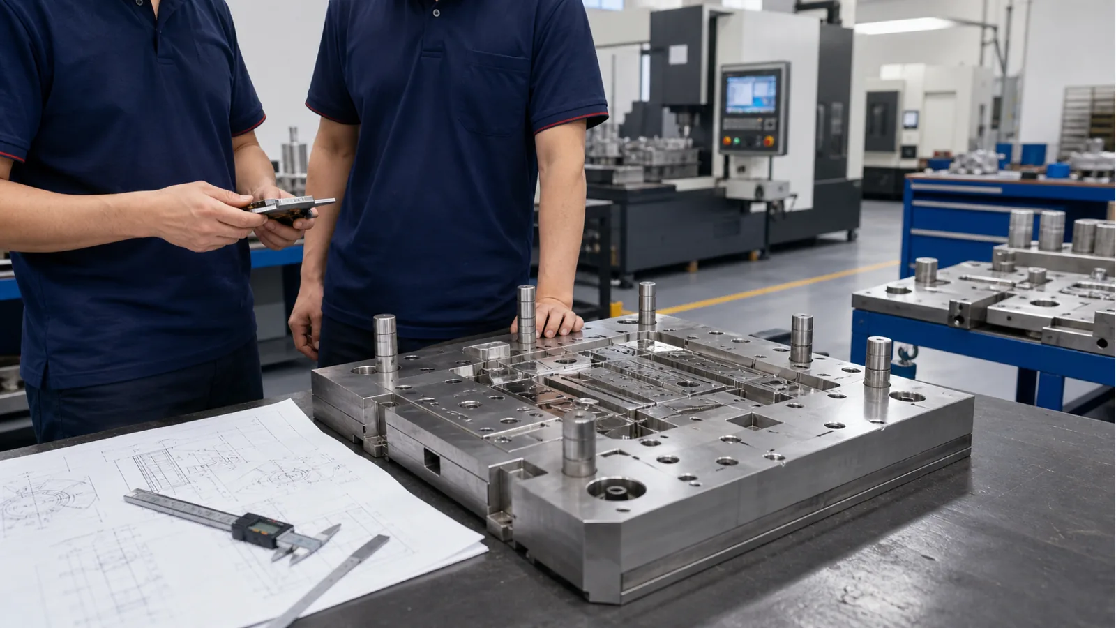
After machining, the mold is assembled and checked by toolmakers. This stage includes fitting inserts, checking sliders and lifters, matching parting surfaces, confirming ejector movement, cleaning cooling channels and checking that all moving parts work smoothly.
Bench work is not just manual finishing. It is a practical check before the first trial. If a slider is too tight, an ejector pin is not smooth or a shut-off does not match correctly, the problem should be corrected before the mold goes into the injection machine.
Step 6: First Mold Trial
The first mold trial is where the design becomes a real molded part. During trial, engineers check whether the mold fills correctly, whether the part can be ejected, whether the dimensions are close to the drawing and whether visible defects appear.
- Short shot or filling imbalance
- Flash around parting line, inserts or shut-off areas
- Sink marks, weld lines, burn marks or flow marks
- Warpage or deformation after cooling
- Ejector marks, drag marks or sticking
- Critical dimensions outside tolerance
A mold trial should produce more than samples. It should produce useful information: material used, machine tonnage, barrel temperature, mold temperature, injection pressure, holding pressure, cooling time, cycle time and inspection notes.
Step 7: Correction, Second Trial and Sample Approval
Very few custom molds are perfect after the first trial. Normal corrections may include polishing, changing gate size, improving venting, adjusting ejector position, modifying steel for dimensions, improving cooling or changing process parameters.
After correction, another trial is arranged. Samples are inspected again, and the customer reviews the parts for fit, appearance and function. For overseas projects, clear photos, inspection reports and notes are important because the customer may not be able to visit the factory before approval.
Typical Lead Time
| Project type | Typical mold lead time | Notes |
|---|---|---|
| Simple small part | 3-4 weeks | Single cavity, common material, no complex side action |
| Medium complexity part | 4-6 weeks | More inserts, sliders, tighter appearance or dimensional requirements |
| Complex functional part | 6-8+ weeks | Multiple sliders, tight tolerance, high polish, complex assembly or repeat testing |
These timelines are general references. The final lead time depends on drawing completeness, customer feedback speed, mold complexity, steel availability and the number of correction rounds after trial.
Where Problems Usually Start
Most tooling problems do not begin in the injection machine. They begin earlier, when important details are not confirmed clearly. A missing tolerance, unclear material, unrealistic wall thickness or late design change can affect mold cost and schedule.
- Customer sends only a 3D file without critical dimensions.
- Material is changed after mold flow, gate and shrinkage decisions are made.
- Cosmetic requirements are not discussed before parting line and gate location are confirmed.
- Production quantity is unclear, so cavity number and mold steel are difficult to choose.
- Assembly requirements are discovered after the first samples are made.
How Yuming Molding Supports Overseas Projects
Yuming Molding works with purchasing managers, product engineers and mold engineers on custom plastic parts and injection mold projects. Our support includes DFM discussion, mold design review, CNC and EDM machining, mold trial, sample feedback, injection molding, inspection and export packaging.
For new projects, we recommend sending the 3D file, 2D drawing, material requirement, target quantity and any appearance or assembly standard. If the design is still early, we can review the part and point out molding risks before formal mold quotation.
FAQ
Can you start mold quotation with only a 3D file?
Yes, we can make an initial review from a 3D file, but a 2D drawing is recommended for final quotation. Critical dimensions, tolerances, material, color, surface finish and quantity affect mold design and cost.
Do all molds need DFM before manufacturing?
For custom parts, DFM is strongly recommended. It helps reduce tooling changes, molding defects and delays after the mold is built.
How many mold trials are normal?
Many molds need one or two trials before approval. Complex parts, tight tolerances or cosmetic parts may need additional correction and testing.
Can you export molds to the United States or Europe?
Yes. We can support export mold requirements, including mold preparation, packing, mold information and communication with overseas customers before shipment.
Leave a Reply